Abstract · This article provides a detailed technical examination of the Solar Rail End Clamp, exploring its design principles, material composition, and critical role in securing photovoltaic modules to mounting rails. The discussion covers load distribution, clamping mechanisms, installation procedures, and the engineering considerations that ensure structural integrity and long-term performance in solar installations.
01. Function and Role in PV Mounting Systems
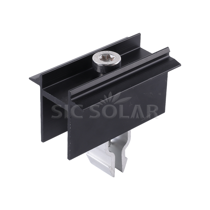
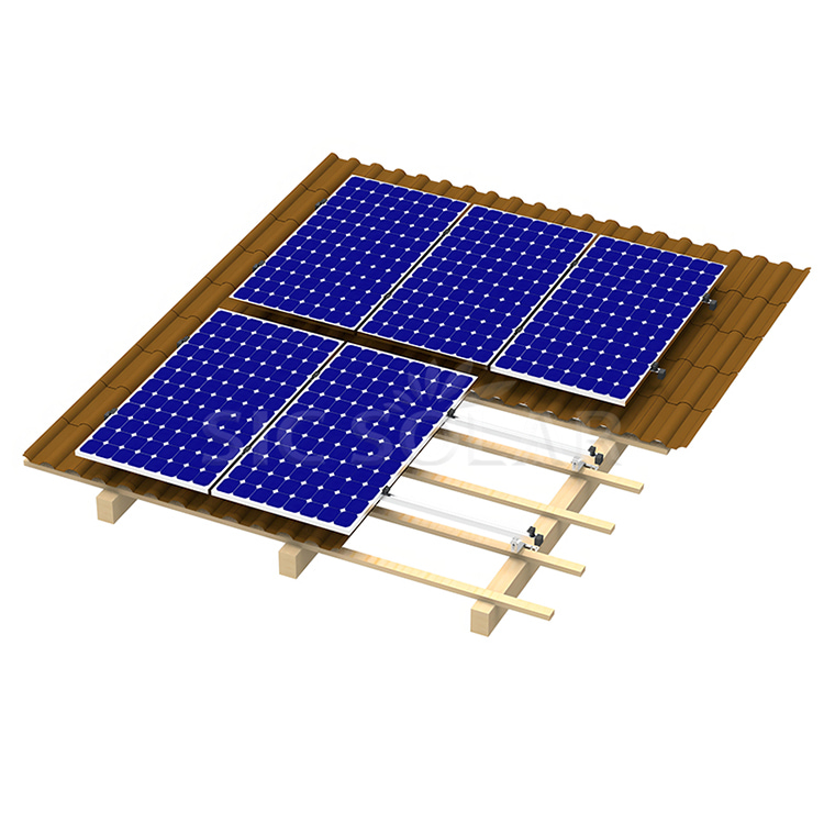
A Solar Rail End Clamp is a specialized fastening component used to secure the outermost edge of a photovoltaic (PV) module to the mounting rail. Unlike mid clamps, which join two adjacent modules, end clamps are positioned at the beginning and end of each module row, gripping only one module frame.
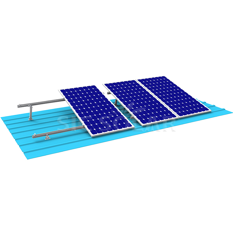
The end clamp plays a critical role in the structural integrity of the entire solar array. It must withstand wind uplift forces, snow loads, and thermal expansion without allowing the module to shift or become dislodged. The clamp transfers these loads from the module frame to the mounting rail, which in turn distributes them to the roof or ground structure. A properly designed end clamp ensures that the module remains securely in place for the 25-year design life of the solar installation.
Secure outer edge of PV module to rail
Withstand wind and snow loads
25 years
02. Material Composition and Corrosion Resistance
High-strength, lightweight, excellent corrosion resistance; anodized for durability
Used for bolts and fasteners; offers superior corrosion resistance
Oxide film of at least 10 μm provides protection against environmental degradation
Designed for outdoor exposure in diverse climates
The Solar Rail End Clamp is typically manufactured from aluminum alloy AL6005-T5, a material widely used in the solar industry for its combination of strength, light weight, and corrosion resistance. The aluminum is anodized to create a protective oxide layer that resists oxidation and environmental degradation. The fasteners—bolts and nuts—are made from SUS304 stainless steel, which provides excellent corrosion resistance and mechanical strength.
03. Mechanical Design and Clamping Mechanisms
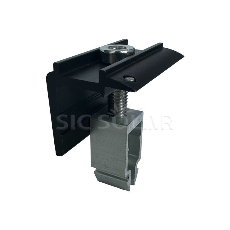
The mechanical design of the Solar Rail End Clamp is optimized to provide secure clamping force while minimizing the risk of damage to the module frame. The clamp typically consists of a body that engages the rail slot, a top plate that contacts the module frame, and a bolt that applies the clamping force.
- Serrated Contact Surface: Some designs include serrations or teeth on the contact surface to penetrate the anodized coating of the module frame, ensuring electrical bonding and preventing slippage.
- T-Slot Engagement: The clamp base is designed to fit into the T-slot of the mounting rail, providing a secure mechanical interlock.
- Load Distribution: The clamp geometry is optimized to distribute clamping force evenly across the module frame, preventing localized stress concentrations.
- Compatibility: End clamps are designed to accommodate various module frame heights, typically ranging from 30mm to 40mm.
Design Note: The clamp must be compatible with the specific rail profile and module frame dimensions. Using an incorrect clamp can lead to inadequate clamping force, module slippage, or damage to the module frame.
04. Load Capacity and Structural Performance
The structural performance of the Solar Rail End Clamp is defined by its ability to withstand the mechanical loads imposed on the solar array. These loads include wind uplift, snow accumulation, and thermal cycling.
| Parameter | Typical Value | Test Standard |
|---|---|---|
| Pullout Resistance | 5 kN or greater | Internal testing |
| Clamping Force | 10–12 N·m torque | Installation specification |
| Wind Load Resistance | Up to 2400 Pa | IEC 61215 |
| Snow Load Resistance | Up to 5400 Pa | IEC 61215 |
| Operating Temperature | -40°C to +85°C | Material specification |
Based on typical specifications for aluminum end clamps.
The pullout resistance of 5 kN indicates the force required to pull the clamp out of the rail slot. This high value ensures that the module remains secure even under extreme wind conditions. The recommended bolt torque of 10–12 N·m provides sufficient clamping force without damaging the module frame.
05. Installation Procedures and Torque Specifications
Proper installation of the Solar Rail End Clamp is essential for ensuring the safety and performance of the solar array. The installation process involves several key steps.
- Positioning: The module is placed on the rails with the outer edge aligned with the end of the rail. The end clamp is positioned at the edge of the module frame.
- Engagement: The clamp base is inserted into the rail T-slot and positioned against the module frame.
- Tightening: The bolt is tightened to the specified torque (typically 10–12 N·m) using a calibrated torque wrench.
- Verification: The installer verifies that the clamp is secure, the module is properly aligned, and the torque is within specification.
- Rail Extension: The rail must extend at least 30mm beyond the module frame to provide adequate space for the end clamp installation.
Installation Note: Always follow the manufacturer's installation instructions and use the specified torque values. Over-tightening can damage the module frame or the clamp; under-tightening can result in insufficient clamping force and module movement. Use a calibrated torque wrench for all critical fastening operations.
06. Quality Standards and Certification Requirements
The Solar Rail End Clamp must meet rigorous quality standards to ensure reliable performance in solar installations. These standards cover material properties, mechanical performance, and environmental durability.
- ISO 9001: Quality management system certification for the manufacturing process.
- UL 2703: Standard for mounting systems, grounding, and bonding equipment for solar panels.
- IEC 61215: Design qualification and type approval for PV modules, including load testing.
- AS/NZS 1170: Structural design actions, including wind and snow loads.
- Material Certification: Certificates of conformity for aluminum alloy and stainless steel components.
- Corrosion Testing: Salt spray testing per ASTM B117 to verify corrosion resistance.
Frequently Asked Questions
Technical specifications and certifications may vary. Always consult the manufacturer's documentation for your specific application requirements.